Primordial Light: Technical
 
Modifying the Draw Tube on a Tele Vue 76 Refractor
to Hold a Heavy Camera
line
 
Above: Many refractors, including older Tele Vue 76mm and 85mm refractors, have a single locking screw on the focuser draw tube locking collar. These collars were meant to carry diagonals or lightweight cameras. There is no reason these smaller telescopes can’t support larger cameras — including a large and heavy CCD camera such as my SBIG STL-11000M — but they can’t safely support such a camera with a single locking screw. Furthermore, with a single locking screw, even if the camera does not slide off the telescope it will not maintain a fixed position relative to the telescope, but will rotate due to its own inertia as the telescope changes attitude during tracking. The solution is obvious and relatively easy: add one or two additional locking screws. If your camera is particularly heavy — my STL-11000M weighs nearly two kg with filters — then two additional locking screws are recommended.
line
Please read this page in its entirety before attempting to carry out this procedure. This modification is not difficult for a person who has a modicum of skill and experience in the use of hand and power tools. This procedure could lead to personal injury and/or damage to your telescope if carried out by an unskilled or careless worker. If you do not have the requisite skill and experience, do not attempt this modification yourself. A machine shop can do it for you at relatively low cost.

Tools needed: a set of hex (Allen) wrenches; a drill press; a #10 or 11/64" drill bit capable of drilling soft aluminum; a center punch; a light hammer; a means of clamping a work piece in the drill press without marring the work piece; a #10-24 tap with small handle (see photo of the tap below).

Materials needed: One or two stainless steel 10-24 screws; light machine oil; mineral spirits. If you cannot find a duplicate of the factory-installed screw use a socket-head screw as shown in the photos below. Even if you have a duplicate of the factory-installed screw, have one stainless steel 10-24 socket-head screw on hand.

Begin by removing the black locking collar from the focusing draw tube. Remove the three black round-headed hex screws that hold the locking collar to the draw tube. Note: the hex wrench needed to remove these screws is very small. Be sure to insert the wrench fully to ensure that it seats properly in the socket before turning; otherwise the socket and/or the wrench may be rounded off and ruined. Put the screws in a sealed container and put them aside to keep them from getting lost. Slide the black locking collar off the brass draw tube by wiggling it ever so slightly. It is not fitted very tightly.

Turn the factory-installed locking screw inward until the brass compression ring is moved a small distance from the inner wall of the locking collar. Insert a fingernail or small, thin, tool under the collar and slide the tool in either direction as needed to facilitate removal of the compression ring. Remove the compression ring and put it in a safe place where it will not be lost or damaged. Remove the factory-installed locking screw and put it in a safe place.

Decide how many additional locking screws you wish to install: one or two. On the inside of the black locking collar measure the distance from the rear plane of the collar—the surface that faces you in the photos above and below—to the center of the channel that retains the compression ring in its position. This is the distance from the rear of the collar at which you will drill. Mark the location(s) where you want to drill. Use the center punch to put a small impression in the aluminum at the drilling point(s). A light tap with the hammer is sufficient. The purpose of this small dimple is to prevent the drill bit from wandering as it starts to bore into the aluminum.

Insert either a #10 (machinist’s size) or an 11/64" drill bit in the drill press chuck. I do not recommend using a hand-held drill for this project unless you are very experienced and you know that you can drill true and without wobble.

Secure the locking collar on the drill-press table. Failure to carry out this important step could result in personal injury and/or damage to the locking collar. The collar could be spun by the drill bit if not secured on the table. The collar should be secured in such a way that it is not marred by the clamp(s) or the metal drill-press table and so that the impression made by the center punch is at top-dead-center: directly below the point of the drill bit. Even though the aluminum you are drilling is quite soft, it is harder than most woods. Drill presses have variable speeds. Consult the drill press manual for proper shaft speed for drilling soft aluminum. Start slowly and feed the bit slowly, ensuring that it starts where you made the impression with the center punch. Ensuring once more that the locking collar is secured to the drill press table so that it cannot move, drill a hole through the collar. Repeat if you are adding two screws.

An inexpensive #10-24 tap.

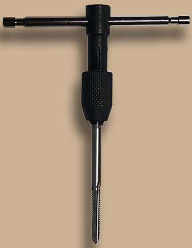
Remove the locking collar from the drill press table. It might be helpful if you can keep it secured with a clamp while you place it on a workbench for the next step, but you may also hold it in your hand. Insert the #10-24 tap in its handle as shown above. Place a single drop of lightweight machine oil on the tap threads.

With the locking collar held firmly by a clamp or in your hand, insert the tapered tap into the hole that you have just drilled. Ensure that the tap is aligned with the hole and not skewed, and begin turning the tap in a clockwise direction (the same way you would turn a screw inward if the hole were already threaded) while pressing firmly on the handle. You will feel the tap being drawn into the hole and you will see tiny aluminum tailings ejected as it begins cutting the threads. Excessive force is not required; the collar is made of aluminum and will tap fairly easily. Continue turning after the tap goes through the hole, but stop short of the region where the tap widens at the top end of the cutter section. You have now cut threads into the hole that you drilled. Turn the tap counter clockwise to remove it. Repeat if you have drilled two screw holes. The first time you insert a screw into the newly threaded hole it will be tight. Even if you have a duplicate of the original screw, place a single drop of lightweight machine oil on the threads of the a 10-24 stainless steel cap-head hex screw. Using a hex wrench and being careful to start the screw straight, insert the screw. Turn it in and out a couple of times. Now you may either leave this screw in place or remove it and insert your duplicate of the manufacturer’s original screw. Repeat for each tapped screw hole.

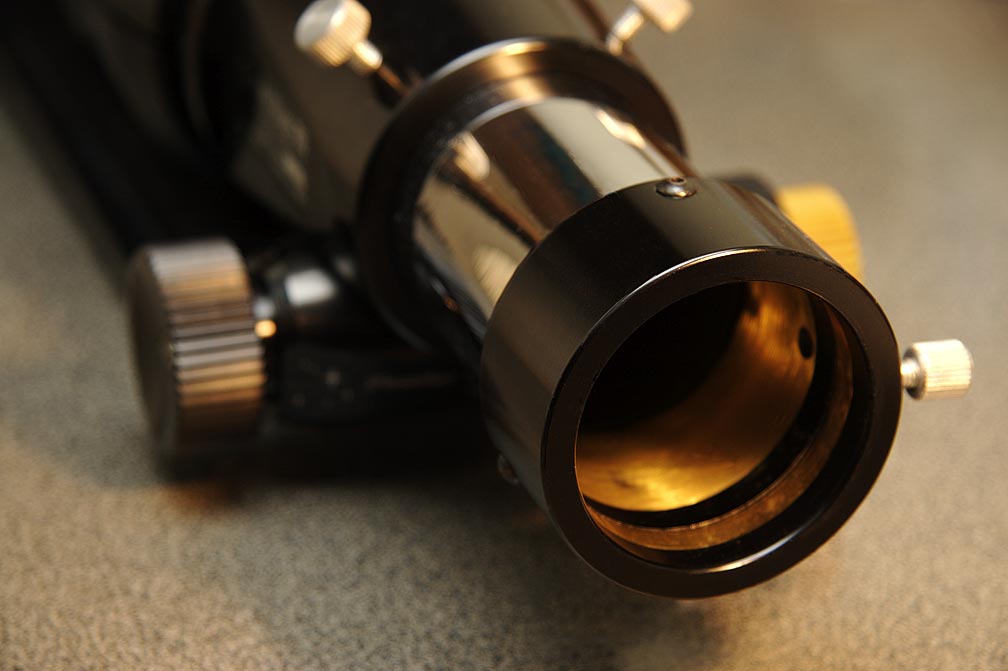
Dampen a soft paper towel or cloth with mineral spirits. Wipe the locking collar thoroughly to remove residual machine oil and aluminum tailings left by the drilling and tapping process. Wipe dry.

Replace the brass compression ring. Back all locking screws out until they are not protruding into the compression-ring channel. Insert the compression ring into the locking collar and let it find its place in the channel. Rotate the compression ring as necessary to ensure that all of the screws press on the ring and not directly on the nosepiece that you will insert into the ring.

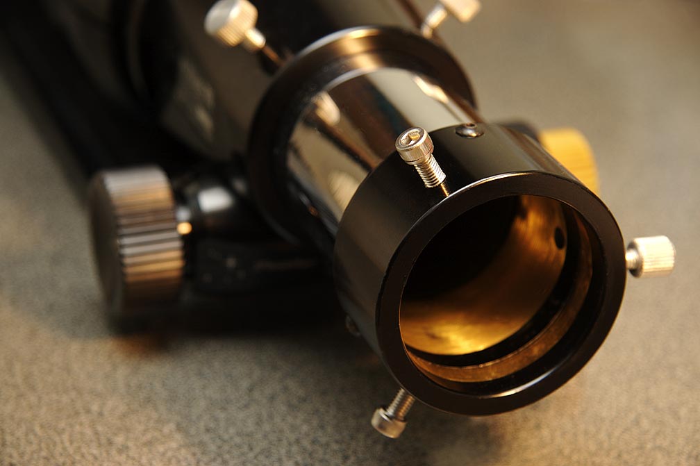
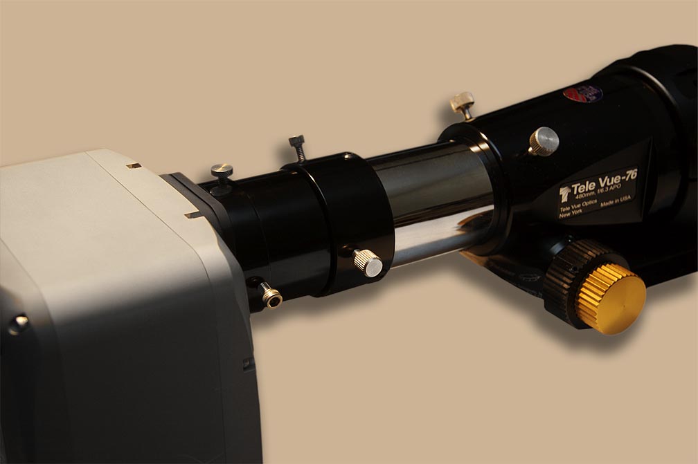
The last step is to reinstall the locking collar on the brass draw tube. Ensure that the manufacturer’s original screw is in its original position. Slide the collar in place and replace the small hex screws, again making sure to insert the very small hex wrench completely so as not to strip the socket.
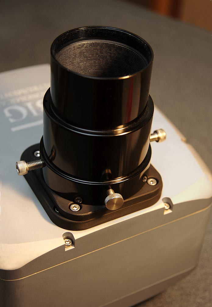
Done.

If you have used socket-head screws as I did, do not over-tighten them with the hex wrench when installing your camera or other accessory. Over-tightening is not a problem with hand-tightened screws.

My Modified Draw Tube Collar

Above: my Tele Vue 76 will not achieve focus with its 2" nose piece inserted directly into the telescope draw tube. It is necessary to use a spacer, as shown above. My spacer also had only one locking screw, so I applied the procedure described above to the spacer as well. The manufacturer’s screw on the spacer is smaller than a 10-24, but I added two 10-24’s. I did not space them at 120° as I did on the telescope locking ring because reaching one of the screws would have been difficult with the camera mounted. I used this spacer as a practice piece for this project; I drilled and tapped the spacer before I undertook the modification of the Tele Vue.

My SBIG STL-11000M securely mounted on my Tele Vue 76. Not shown: two strong cords attached to the STL-11000M handles for extra protection against the camera falling. Such cords should always be used when a camera is held in place by pressure from set screws or thumb screws as shown above.